Dynamic blocks are incredibly powerful, allowing you to create more versatile and intelligent drawings. They save time by reducing the need for multiple block definitions and enable easy adjustments without redrawing elements from scratch.
One common issue you might face is ensuring that elements within a dynamic block maintain their relationships when modifying the block. This is a little tricky but when done correctly, it will save you a ton of time. We actually were able to help one of you with his/her dynamic block facing this instance.
We started by drawing the primary shape or element included in the dynamic block. This could be anything from architectural components to mechanical parts.
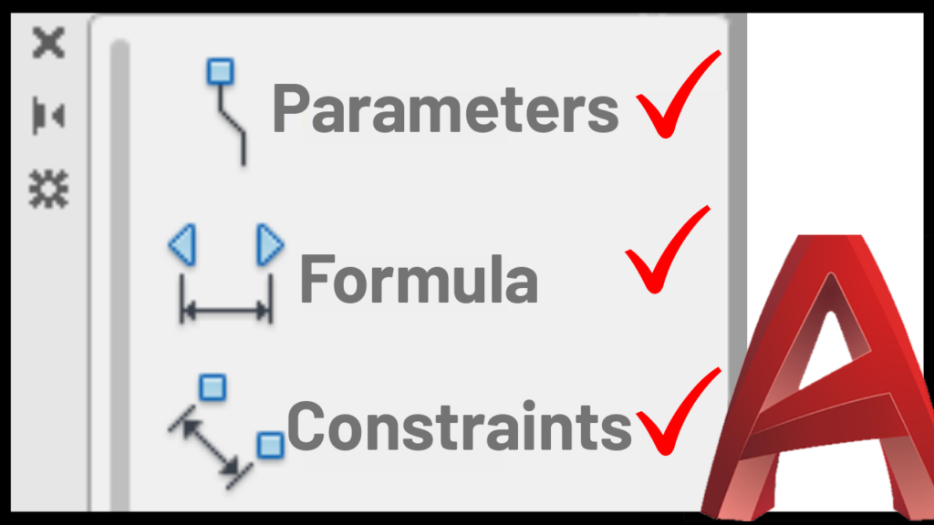
Then we used AutoCAD’s Block Editor to add parameters and actions to the block. For instance, if you want to create a block with adjustable sizes, you can use the ‘Linear’ parameter along with the ‘Stretch’ action. This allows you to resize the block dynamically without altering the core design.
After that, we implemented geometric constraints such as the ‘Equal’ constraint to ensure elements within the block maintain their proportions as the block is resized. This is particularly useful for maintaining symmetry or specific dimensional relationships.
i Know this staff sounds advanced, but once you understand this technique you can apply it and implemented in any of your blocks to streamline your AutoCAD workflow, reduce errors, and produce more flexible designs.
To see these techniques in action, watch the below video that provides full instructions on how to apply these methods to your blocks.